.png) Português
Português


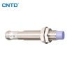
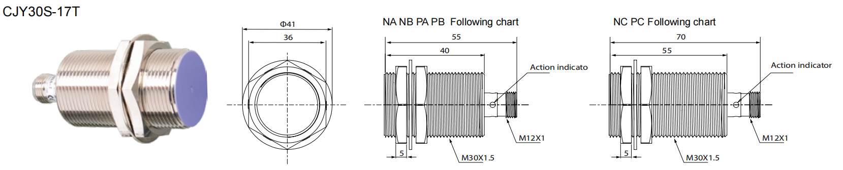
CJY30S-17T

◼Long sensing distance (1.5 to 2 times longer sensing distance
guaranteed compared to existing models)
◼Exclusively designed IC for improved the noise resistance
◼Inside surge protection, reverse polarity protection, overcurrent protection
◼Long use-life cycle and high reliability, easy install, enconomic price
◼Red LED status indication, easy to confirm work situation
◼Protection structure IP65(IEC standard)
◼Replaceable for limit switches
|
Item |
Code |
Description |
|
1Company code |
C |
Company code |
|
2Product name |
J |
Inductive proximity sensor |
|
3 Shape of shell |
Y |
Cylinder-shaped |
|
4 Dimension code |
12 |
12=M12 |
|
5 Product type |
S |
Long-range type |
|
6 Detection distance |
07 |
07=7mm |
|
7Output mode |
K |
AC 2wires |
|
L |
DC 2wires |
|
|
P |
PNP 3wires |
|
|
N |
NPN 3wires |
|
|
8 Output state |
A |
NO |
|
B |
NC |
|
|
C |
NO+NC |
|
|
9 Connection |
Without |
Without: Lead wire |
|
T |
Plug-in |
|
|
R |
Wiring leads Plug-in |
DC 3-wire type
|
Model |
CJY12S-04NAT CJY12S-04NBT CJY12S-04NCT CJY12S-04PAT CJY12S-04PBT CJY12S-04PCT |
CJY12S-07NAT CJY12S-07NBT CJY12S-07NCT CJY12S-07PAT CJY12S-07PBT CJY12S-07PCT |
CJY18S-10NAT CJY18S-10NBT CJY18S-10NCT CJY18S-10PAT CJY18S-10PBT CJY18S-10PCT |
CJY18S-15NAT CJY18S-15NBT CJY18S-15NCT CJY18S-15PAT CJY18S-15PBT CJY18S-15PCT |
CJY30S-17NAT CJY30S-17NBT CJY30S-17NCT CJY30S-17PAT CJY30S-17PBT CJY30S-17PCT |
CJY30S-25NAT CJY30S-25NBT CJY30S-25NCT CJY30S-25PAT CJY30S-25PBT CJY30S-25PCT |
|
Sensing distance |
4mm |
7mm |
10mm |
15mm |
17mm |
25mm |
|
Hysteresis |
Max.10%of sensing distance |
|||||
|
Standard sensing targe |
12×12×1mm (Iron) |
25×25×1mm (Iron) |
20×20×1mm (lron) |
40×40×1mm (Iron) |
45×45×1mm (Iron) |
75×75×1mm (Iron) |
|
Setting distance |
0~2.8mm |
0~5.6mm |
0~4.9mm |
0~9.8mm |
0~10.5mm |
0~17.5mm |
|
Power supply (Operating voltage) |
12-24VDC(10-30VDC) |
|||||
|
Leakage current |
Max.10mA |
|||||
|
Response frequency (※1) |
400Hz |
300Hz |
300Hz |
200Hz |
100Hz |
100Hz |
|
Residual yoltage |
Max.1V |
|||||
|
Affection by Temp |
Max.±10%for sensing distance at ambient temperature 20C |
|||||
|
Control output |
Max.200mA |
|||||
|
Insulation resistance |
Min.50MΩ(at 500VDC megger) |
|||||
|
Dielectric strengtt |
1500VAC 50/60Hz for 1minute |
|||||
|
Vibration |
1mm amplitude at frequency of 10 to 55Hz(for 1 min.)in each of X,Y,Z directions for 2 hours |
|||||
|
Shock |
500m/s²(approx.50G)X,Y,Z directions for 3 times |
|||||
|
Indicato |
Operation indicator(red LED) |
|||||
|
Ambient temperature |
-25~+70℃(No icing) |
|||||
|
Storage temperature |
-30~+80℃(No icing) |
|||||
|
Ambient humidity |
35~95%RH (No condensation) |
|||||
|
Protection circuit |
Surge protection circuit,Reverse polarity protection circuit,Overcurrent protection circuit |
|||||
|
Material |
Case/Nut:Nickel plated Brass,Washer:Nickel plated Iron,Sensing surface:PBT |
|||||
|
Protection |
IP65 |
|||||
(※1) The response frequency is the average value. The standard sensing target is used and the width is set as 2 times of the standard sensing target, 1/2 of the sensing distance for the distance.

|
Mutual-interference When several proximity sensors are mounted close to one another a malfunction of the sensor may be caused due to mutual interference. Therefore, be sure to provide a minimum distance between the two sensors as below chart indicates. |
Influence by surrounding metals When sensors are mounted on metallic panel, you must prevent the sensors from being affected by any metallic object except target. Therefore, be sure to provide a minimum distance as below chart indicates. |

|
Model |
CJY12S-04T |
CJY12S-07T |
CJY18S-10T |
CJY18S-15T |
CJY30S-17T |
CJY30S-25T |
|
A |
24 |
48 |
42 |
84 |
90 |
150 |
|
B |
24 |
36 |
36 |
54 |
60 |
90 |
|
e |
0 |
11 |
0 |
14 |
0 |
15 |
|
φd |
12 |
36 |
18 |
54 |
30 |
90 |
|
m |
12 |
24 |
21 |
42 |
45 |
75 |
|
n |
18 |
36 |
27 |
54 |
45 |
90 |