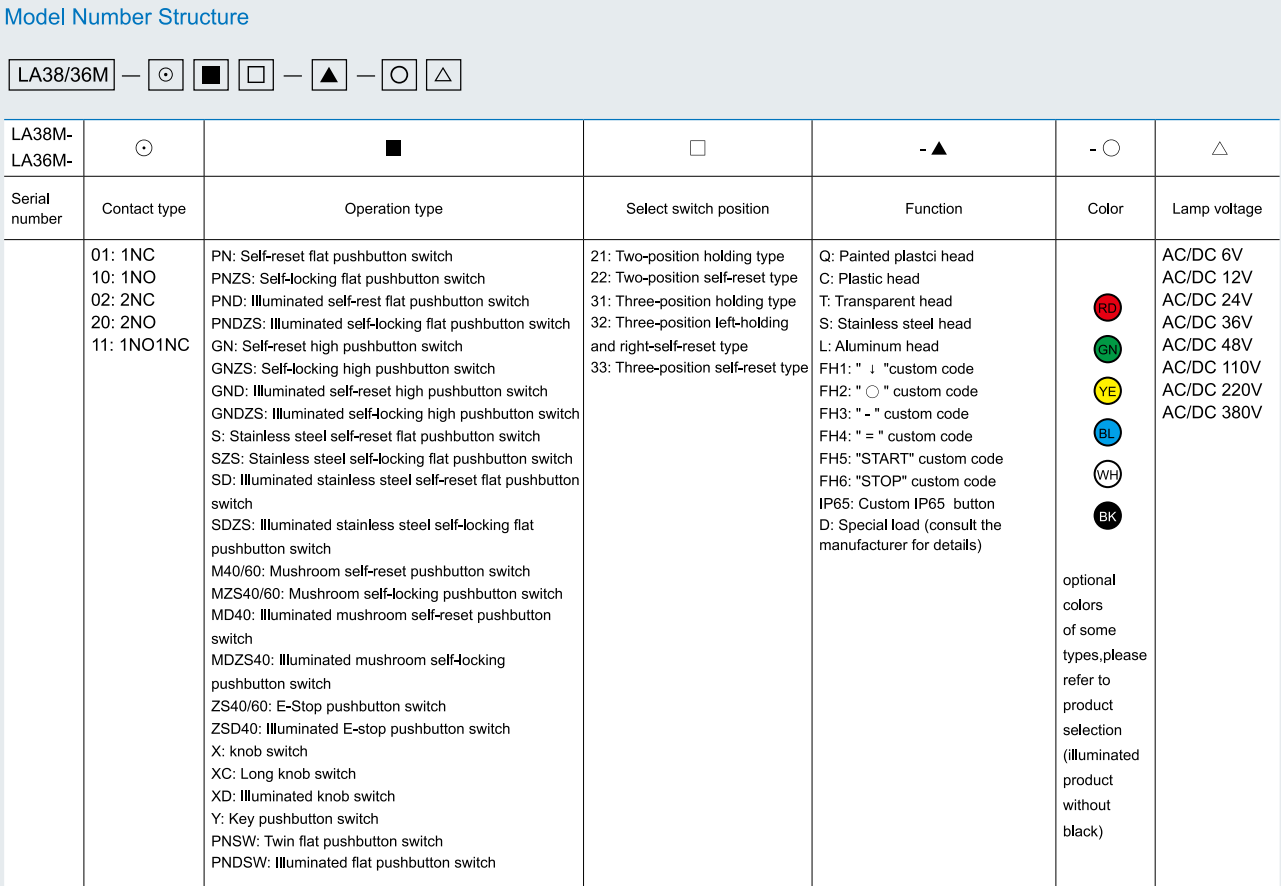
.png) Português
Português


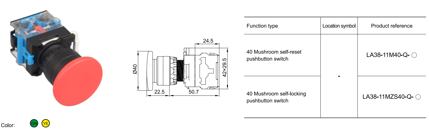
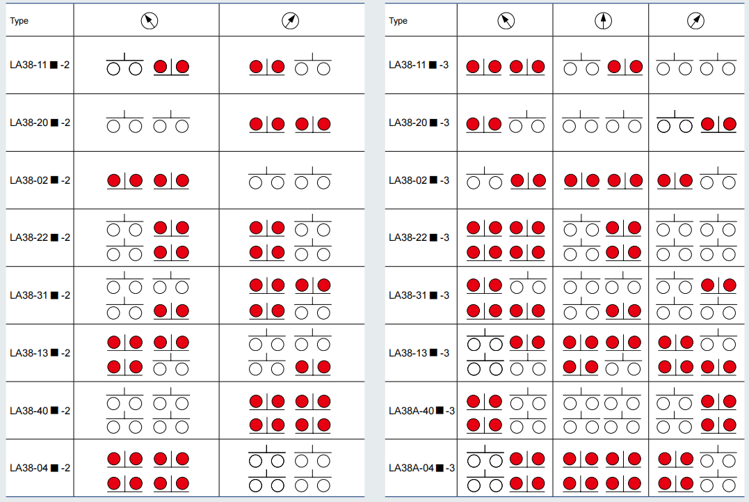
LA38-11M40-Q
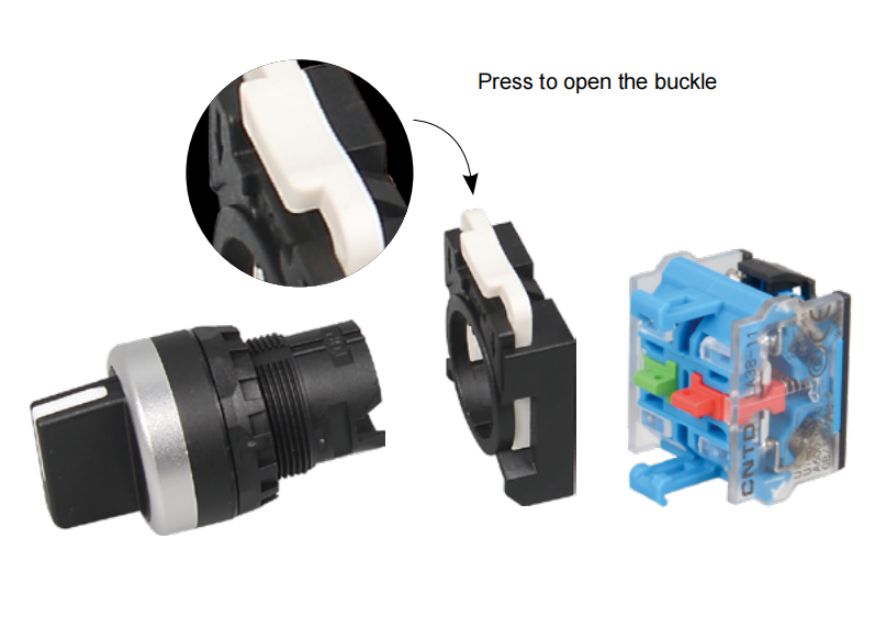
The three-position knobs need to be installed directionally(look for ‘TOP’) ,others don`t .
Switch Ratings
|
Rated insulation voltage Ui |
600V |
||||||
|
Rated thermal current Ith |
10A |
||||||
|
Rated operational voltage Ue |
24V |
48V |
110V |
220V |
380V |
||
|
Rated operational current Ie |
AC 50/60Hz |
Resistive load |
10A |
- |
10A |
6A |
- |
|
Inductive load |
10A |
- |
6A |
3A |
2A |
||
|
DC |
Resistive load |
8A |
4A |
2.2A |
1.1A |
- |
|
|
Inductive load |
4A |
2A |
1.2A |
0.6A |
- |
||
|
Contact material |
Silver alloy |
||||||
|
Ambient temperature |
-25℃ ~+75℃ (With no icing) |
|
Humidity |
45~85%RH |
|
Contact resistance |
≤50mΩ |
|
Insulation resistance |
≥100MΩ |
|
Power frequency withstand voltage |
1890VAC/50Hz/60s |
|
Vibration resistance |
Amplitude: about 1.0mm/50Hz |
|
Impact resistance |
> 10g |
|
Degree of protection |
IP40 |
|
Electrical life |
≥100,000 times |
|
Wiring capacity |
Maximum: 2×1.5mm² or 1×2.5mm², Minimun: 2×0.75mm², Maximum insert: 6.3×0.8mm |
LED Specifications
|
LED type |
Bidirectional LED |
||
|
Rated voltage |
AC/DC 6V |
AC/DC 12V |
AC/DC 24V |
|
AC/DC 36V |
AC/DC 48V |
AC/DC 110V |
|
|
AC/DC 220V |
AC/DC 380V |
|
|
|
AC 110V |
AC 220V |
AC 380V |
|
|
Emitting color |
RD GN YE BL WH BK |
||
|
Life |
≥40000h |
||
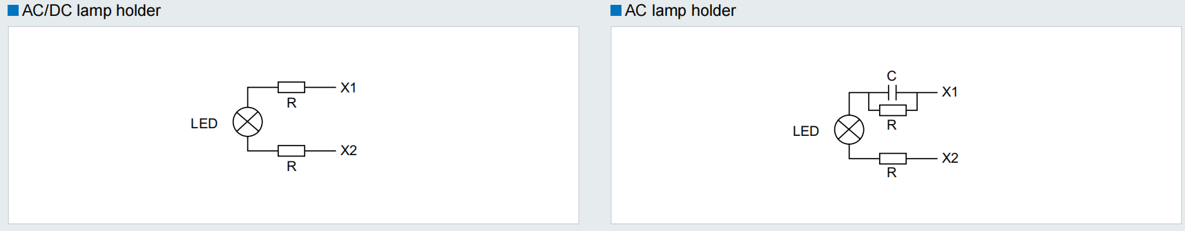
Lamp Holder Circuit Schematic
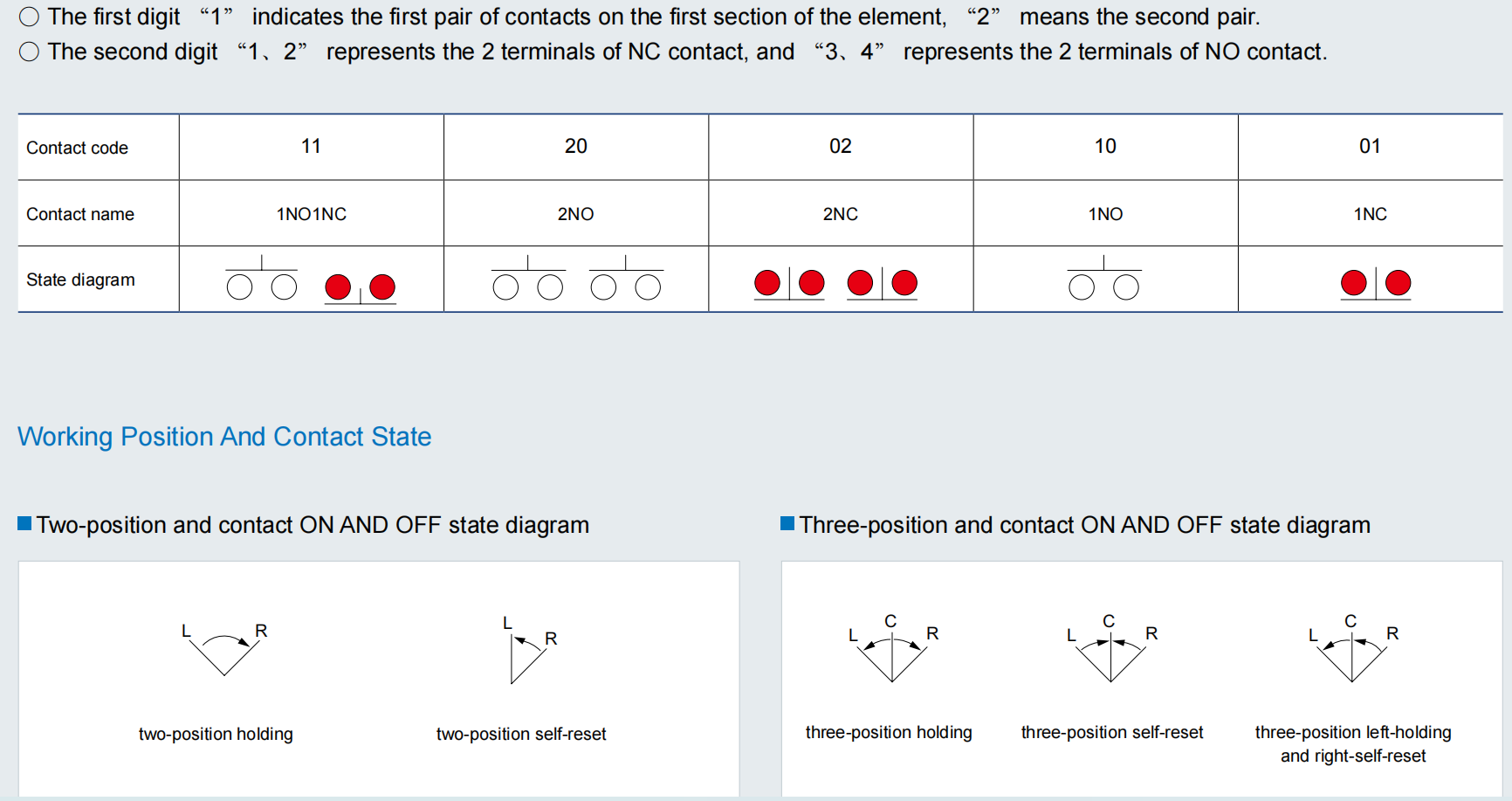
Contact Form Description
◼The two digits in the model number represent the contact form
○ The first digit “1” indicates the first pair of contacts on the first section of the element, “2” means the second pair.
○ The second digit “1、2” represents the 2 terminals of NC contact, and “3、4” represents the 2 terminals of NO contact.
Related Products


