.png) Português
Português


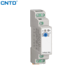


CME1/CME2/CME4 One Channel/Two Channel/Four Channel Temperature Controller Module

◼With multi-channel temperature control function, one module
is equivalent to multiple temperature control meters, and
the temperature control parameters of each channel are
independent and do not affect each other.;
◼Multi-channel intelligent temperature control algorithm, can
achieve 4-channel accurate PID temperature control, can be
widely used in a variety of heating models;
With RS485 communication interface, standard modbus RTU
communication protocol, easy to communicate with PLC or
configuration screen, online monitoring of temperature data,
real-time control by the host equipment;
◼Modular structure design, optional multi-module splicing method,
multiple temperature control modules are spliced through the
side quick socket to achieve the effect of doubling the number
of channels, multiple 4-channel modules can be spliced into
8-channel, 16-channel and more temperature control channels;
◼The product has a high degree of integration and compact
size. The rail-type installation method is suitable for installation
places such as on-site control cabinets and power distribution
cabinets.;
|
① Company name |
C |
CNTD |
|
② Series |
ME |
Standard modular thermostat |
|
MH |
High-precision modular thermostat |
|
|
③ Number of channels |
1 |
Single channel |
|
2 |
Dual channel |
|
|
4 |
Four channels |
|
|
8 |
Eight channels |
|
|
12 |
Twelve channels |
|
|
④ Power supply voltage |
2 |
24V AC 50/60Hz,18-32VDC |
|
4 |
100-240V AC,50/60Hz |
|
|
⑤ Temperature input |
K |
Thermocouple (K, E, J, L, T, R, S) |
|
P |
Thermal resistance input (PT100, Cu50) |
|
|
A |
4-20mA input |
|
|
⑥ Control output |
1 |
Relay |
|
2 |
SSR output |
|
|
A |
0-20mA、4-20mA |
|
|
B |
0-5V、1-5V |
|
|
⑦ Communication |
N |
No communication output |
|
R |
RS485 communication |
|
|
⑧ Combination quick connection interface |
None |
No quick connection |
|
1 |
Quick connect input on the left |
|
|
2 |
Quick connect output on the right |
|
|
3 |
Left and right quick connection input and output |
|
Rated voltage |
100-240V AC,50Hz |
|
Power consumption |
≤5VA |
|
Working environment |
Ambient temperature: 0℃ -50℃ Relative humidity: 35%-85% (no condensation) |
|
Storage temperature |
-25℃ -65℃ (avoid freezing or condensation) |
|
Resolution |
1℃ , 0.1℃ (adjustable) |
|
Wiring method |
Terminal block |
|
Detection accuracy |
±0.5%FS |
|
Memory protection |
Non-volatile memory |
|
Relay output (If the control output is a relay) |
Relay contact AC220V/DC30V, 3A |
|
Relay logic level output (If the control output is SSR) |
When ON: DC12V; when OFF: below DC0.5V; Maximum current: 30mA, load resistance ≥ 1K |
|
Thermocouple input type |
K、E、J、L、T、R、S |
|
Thermal resistance input type |
PT100、Cu50 |
Please refer to the wiring diagram on the side of the modular thermostat for the wiring method. The following is the explanation of the
terms on the wiring diagram.:

|
L、N |
Thermostat AC220V power supply input interface, can not be divided into zero line, firewire |
|
NTC |
External cold terminal detection, can be connected to the included cold terminal resistor, the port does not distinguish between positive and negative.If the external cold terminal resistor is not connected, the internal cold terminal is automatically used |
|
RS485 |
485 communication interface, you need to distinguish between positive and negative electrodes, A+, B- |
|
TC1 |
The thermocouple input signal of channel 1, the positive and negative electrodes need to be distinguished |
|
SSR1 |
The solid-state drive signal output of channel 1, the positive and negative electrodes need to be distinguished |
|
AIN1 |
The analog input of channel 1, the default is 4-20mA signal, the positive and negative electrodes need to be distinguished |
|
AOUT1 |
The analog output of channel 1, the default is 4-20mA signal, the positive and negative electrodes need to be distinguished |

ALM alarm parameter definition
|
Alarm code |
Alarm form |
Description |
|
0 |
No alarm |
No alarm output |
|
1 |
Absolute upper limit alarm |
Alarm when PV>ALUP |
|
2 |
Alarm at the lower absolute value |
Alarm when PV |
|
3 |
Deviation upper limit alarm |
Alarm when PV>SV+ALUP |
|
4 |
Alarm of the lower deviation limit |
Alarm when PV |
|
5 |
Alarm within the absolute value range |
Alarm when PV |
|
6 |
Alarm outside the absolute value range |
Alarm when PV>ALUP or PV |
|
7 |
Alarm within the deviation range |
Alarm when PV |
|
8 |
Alarm outside the deviation range |
Alarm when PV>SV+ALUP or when PV |
|
9 |
Absolute upper limit alarm (hold) |
Alarm when PV>ALUP |
|
10 |
Alarm at the lower absolute value (hold) |
Alarm when PV |
|
11 |
Deviation upper limit alarm (hold) |
Alarm when PV>SV+ALUP |
|
12 |
Alarm of the lower limit of deviation (hold) |
Alarm when PV |
Enter the indexing number type selection

Dimensional diagram

Related Products


