.png) Português
Português


CTI

◼Independent high-precision sampling of each channel;
◼Has a variety of alarm logic judgment modes;
◼Wide operating voltage, compatible with DC12-28V power
supply;
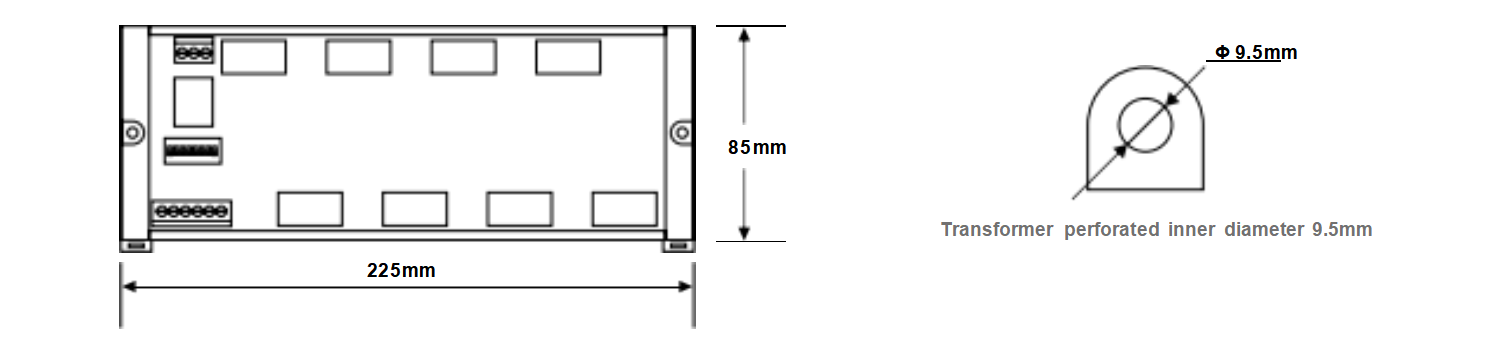
◼Sufficient threading spacing is reserved between the transformers
to facilitate wiring maintenance;
◼High-stability design, long-term operation without manual
intervention;
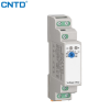
Overview
CTI series current monitoring module is a multi-channel AC
current real-time monitoring and acquisition module. By
collecting the signal waveform of a high-precision current
transformer, the built-in 32-bit high-performance main control
unit calculates the effective current value in real time, and can
realize a variety of alarm logic according to user settings.Using
RS-485 communication bus, data transmission is carried out
through the standard MODBUS-RTU protocol.
|
No |
Item |
Description |
|
① |
CTI |
Current module |
|
② |
8 |
Number of current detection channels 4: Four-way 6: Six ways 8: Eight ways |
|
③ |
100A |
Upper range limit |
Technical parameters
|
Supply voltage: DC12-28V |
Power consumption: ≤ 1.5W |
|
Working temperature: -20℃ ~ 50℃ |
Working humidity: 15%~90% (no condensation) |
|
Detection resolution: 0.1A |
Basic error: ±1%FS |
|
Sampling period: 100ms |
Overcurrent capacity: range 150% |
|
Input signal: 9~30V |
Relay contact: AC220V/DC30V, 3A |
|
Range range: 50A, 100A |
|
Dimensions
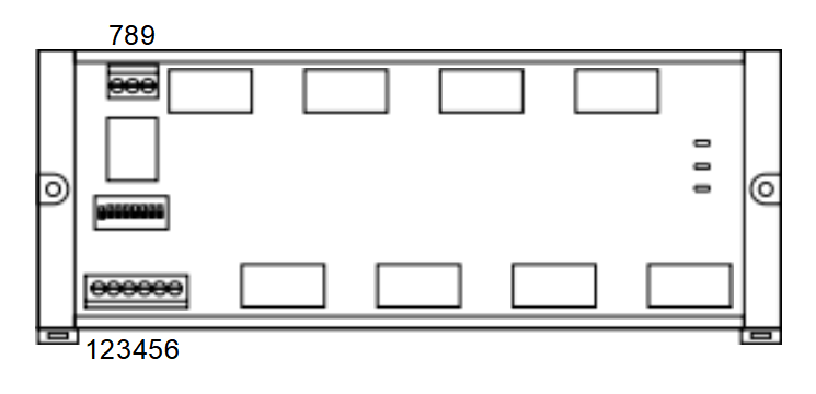
Terminal definition
Terminal 1: the positive electrode of the module’s power supply
Terminal 2: Negative electrode of module power supply
Terminal 3: RS485+
Terminal 4: RS485-
Terminal 5: Input signal INA
Terminal 6: Input signal INB
Terminal 7: Normally closed terminal of relay
Terminal 8: Common terminal of relay
Terminal 9: Relay normally open
Dial code setting
The 8th bit of the dial code of the current monitoring module is used to select the communication parameters.
When the 8th dial code is set to ON, the communication baud rate is 9600, and 8N1 has no verification.At this time, the communication
address is determined by dialing code 1-dialing code 7. We regard dialing code ON as a value of 1 and dialing code OFF as a value of 0.:
Mailing address = Dial code 1+ (dial code 2×2) + (dial code 3×4) + (dial code 4×8) + (dial code 5×16) + (dial code 6×32) + (dial code
7×64)
If the 8th bit dial code is set to OFF, the communication address, baud rate, parity bit and other parameters are determined by the
registers 202, 203, and 204 (see register definition for details)
Note: After adjusting the communication parameters, the module needs to be restarted to take effect!
Indicator light description
There are three indicators on the right side of the module to identify the working status.
RUN: Running state, long light indicates that the alarm is allowed, and the alarm judgment is prohibited when the short flicker is on;
COM: Communication status, flashing during communication;
ALARM: Alarm status, there is an alarm for a long time to light up;